Understanding EMP Threats to Radio Communications
On September 1, 1859, the sun's surface erupted with unprecedented violence. A massive coronal mass ejection hurtled toward Earth at millions of miles per hour. When it struck our planet's magnetosphere thirty-three hours later, telegraph systems across Europe and North America sparked and shocked operators. Some caught fire. Papers ignited spontaneously at telegraph stations. The aurora borealis blazed as far south as the Caribbean, visible in Cuba and Jamaica. This Carrington Event demonstrated nature's capacity to weaponize electromagnetic energy against our technology. Today, our dependence on solid-state electronics exceeds Victorian-era telegraph systems by orders of magnitude. The threat of electromagnetic pulse events—whether natural or man-made—represents one of the most catastrophic vulnerabilities facing modern communications infrastructure.
An electromagnetic pulse, or EMP, manifests through three distinct phases. Each targets different aspects of electronic systems with devastating precision. The E1 pulse arrives first, lasting mere nanoseconds but carrying tremendous energy. Gamma radiation interacts with air molecules in the upper atmosphere. This interaction generates a powerful electromagnetic field that induces voltage spikes in conductors—antennas, power lines, and circuit traces alike. The E1 component specifically targets semiconductor junctions in modern solid-state devices. Voltage differentials of just a few volts can cause catastrophic breakdown at these junctions.
Following milliseconds behind, the E2 pulse resembles lightning in its characteristics. It arrives in an environment already compromised by E1 damage. The E3 pulse develops over seconds to minutes, inducing currents in long conductors like power transmission lines. This component can destroy transformers and grid infrastructure .
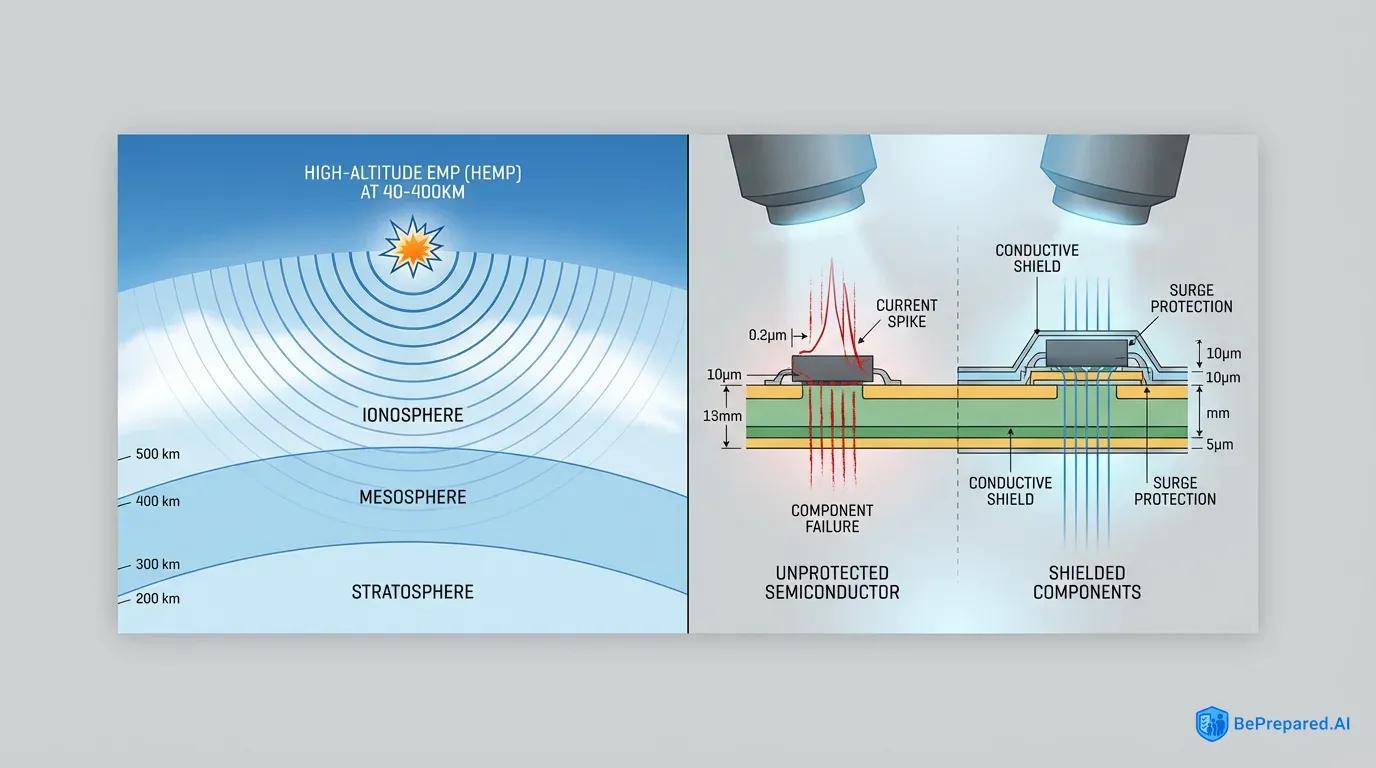
High-altitude electromagnetic pulse (HEMP) occurs when a nuclear device is detonated at altitudes between 40 and 400 kilometers . At these heights, the weapon's gamma radiation interacts with the thin upper atmosphere. Physicists call this the Compton effect—electrons stripped from air molecules by gamma photons spiral along Earth's magnetic field lines. This generates an intense electromagnetic cascade. A single high-altitude nuclear detonation over the central United States could potentially affect electronics across the entire continental landmass.
The altitude matters critically. Too low, and the atmosphere absorbs much of the gamma radiation before it can generate the electromagnetic cascade. Too high, and the thin atmosphere provides insufficient material for interaction. The 40-400km range maximizes the affected ground area while generating maximum pulse intensity .
Natural EMP events, primarily coronal mass ejections from the sun, follow different physics but achieve similar destructive results. These events lack the sharp E1 component that makes nuclear EMP so devastating to semiconductors. Instead, they generate primarily E3-type effects that induce currents in long conductors. The 1859 Carrington Event represented an extreme example, but solar storms of varying intensity strike Earth regularly.
In March 1989, a geomagnetic storm induced currents in Quebec's power grid. The entire system collapsed, leaving millions without electricity for nine hours. The storm caused transformer damage that took months to repair. Scientists estimate a Carrington-class event today would cause trillions of dollars in damage and require years for full infrastructure recovery.
The vulnerability of modern electronics stems from the physics of semiconductor operation. Transistors, integrated circuits, and microprocessors function by controlling tiny currents through precisely engineered junctions between different types of silicon. These junctions operate with voltage tolerances measured in single-digit volts. When an EMP induces voltage spikes of hundreds or thousands of volts in connected conductors—antennas being particularly efficient EMP collectors—those spikes propagate into semiconductor junctions faster than any protection circuit can respond.
The junction experiences what engineers call "overvoltage breakdown." The semiconductor material's crystal structure suffers permanent damage. A transistor that operated perfectly at 3.3 volts becomes useless scrap silicon in nanoseconds.
Solid-state amateur radio equipment incorporates thousands of these vulnerable junctions. Modern transceivers use semiconductor technology throughout their signal paths: voltage-controlled oscillators, mixer diodes, RF amplifier transistors, and digital signal processors. Each represents a potential failure point. The miniaturization that makes contemporary ham radio equipment compact and feature-rich simultaneously increases EMP vulnerability.
Smaller semiconductor geometries mean thinner insulating layers and lower voltage tolerances. A modern microprocessor with transistors measured in nanometers exhibits far greater EMP susceptibility than discrete transistors from the 1970s. Those older components featured junction geometries measured in micrometers.
Vacuum tube technology operates on fundamentally different principles that provide inherent EMP resistance. Tubes control electron flow through a vacuum using electric fields rather than semiconductor junctions. The electrons travel through empty space rather than solid material. The controlling grids tolerate voltage swings of hundreds of volts as part of normal operation.
An EMP can certainly damage vacuum tube equipment—particularly if it destroys associated components like transformers or capacitors. However, the tubes themselves demonstrate remarkable resilience. The same robust construction that allowed tube equipment to survive the mechanical shocks of military deployment provides natural protection against electromagnetic assault. This distinction between vacuum tube and solid-state vulnerability forms the foundation of EMP-resistant amateur radio strategy.
EMP-Resistant Ham Radio Technologies
Walking into a modern amateur radio station reveals racks of sleek transceivers, computer-controlled antenna tuners, and digital displays showing waterfall spectrum analyzers. The technology represents decades of advancement in sensitivity, selectivity, and feature integration. Yet this same advancement creates a paradox for the preparedness-minded operator: the more sophisticated the radio, the more vulnerable it becomes to electromagnetic pulse events.
Understanding the technological approaches to EMP resistance requires examining not just individual components, but entire design philosophies. These philosophies separate survivable equipment from potential paperweights.
Vacuum tube technology dominated amateur radio from the hobby's inception through the 1970s. These older designs offer the most straightforward path to EMP resistance. The physical construction of vacuum tubes provides multiple layers of inherent protection. The tube envelope itself—whether glass or ceramic—provides electrical isolation between the internal elements and external electromagnetic fields.
The tube's internal structures consist of relatively massive metal elements compared to semiconductor junctions. The cathode, grid, and plate can absorb significant induced currents without damage. Most critically, vacuum tubes operate at high voltages as part of their normal function. A typical tube amplifier might run plate voltages of 300-800 volts. The tube is designed to handle these potentials continuously.
When an EMP induces voltage spikes in the antenna or power supply leads, the tube circuitry often absorbs these transients within its normal operating envelope.
The support circuitry surrounding vacuum tubes also exhibits greater robustness than modern equivalents. Tube equipment uses large transformers with heavy wire windings. High-voltage capacitors are built to withstand continuous stress. Discrete resistors are rated for substantial power dissipation. These components don't just tolerate EMP-induced transients better than their miniaturized modern counterparts—they often actively limit the transients through their inherent impedance.
A power transformer's inductance naturally opposes rapid current changes. This provides a degree of filtering against fast-rising EMP pulses. Large filter capacitors absorb voltage spikes that would destroy the tiny ceramic capacitors in modern switching power supplies.
Vacuum tube equipment isn't invulnerable. The tubes themselves may survive, but associated components can fail. Selenium rectifiers, common in vintage equipment, can short circuit under voltage stress. Paper and oil capacitors degrade over time and may fail catastrophically when stressed.
If the equipment is connected to an antenna during an EMP event, the tremendous RF energy collected by the antenna can arc over tube sockets. It can destroy variable capacitors and burn out tank coils. The tube radio's EMP resistance primarily applies to equipment stored disconnected from antennas and power sources—a critical limitation for maintaining communications capability during an event.
Military-grade EMP protection represents a different technological approach. It employs active hardening measures rather than relying on component robustness. The Department of Defense developed MIL-STD-188-125 standards specifically to ensure communications equipment survives nuclear EMP effects. Equipment meeting these standards incorporates multiple protection layers: shielded enclosures that attenuate incoming electromagnetic fields, filtered power inputs that block conducted transients, and protected antenna connections using gas discharge tubes and fast-acting solid-state suppressors .
The protection philosophy assumes the equipment will be powered and connected to antennas during an EMP event. This requires active suppression rather than passive survival.
The implementation of military-grade protection involves sophisticated engineering. Shielding effectiveness requires conductive enclosures with properly designed seams, gaskets, and penetrations. Simply placing equipment in a metal box provides minimal protection if electromagnetic energy leaks through gaps or enters via cables. Military specifications demand that all cables entering the protected volume pass through filtered connectors. Series inductors and shunt capacitors create low-pass filters that block high-frequency EMP components while passing desired signals.
Antenna connections require special attention. The antenna itself acts as an EMP collector. Military equipment uses multiple stages of protection: gas discharge tubes that ionize and conduct when voltage exceeds safe thresholds, followed by fast-acting semiconductor suppressors that clamp remaining transients. Finally, series resistors or ferrite beads limit current flow into sensitive circuits.
Modern amateur radio manufacturers have begun incorporating EMP-resistant design elements. Few meet full military specifications. The challenge lies in balancing protection with performance and cost. Heavy shielding adds weight and expense. Extensive input filtering can degrade receiver sensitivity or limit transmitter output.
Some manufacturers take a middle path. They incorporate partial protection that improves survivability without the expense of full military hardening. These designs might include shielded enclosures, basic input filtering, and semiconductor protection on antenna ports. These measures significantly improve EMP resistance compared to unprotected equipment, even if they don't guarantee survival under all scenarios.
Faraday cage compatibility represents another critical aspect of EMP-resistant technology. A Faraday cage—an electrically conductive enclosure—blocks external electromagnetic fields from reaching its contents. The cage only protects equipment stored inside while disconnected from external antennas and power. The compatibility question becomes: can the radio be rapidly deployed from protected storage and made operational?
Equipment requiring extensive setup, computer programming, or connection to external devices presents operational challenges. Simpler designs that can be removed from a Faraday cage, connected to a pre-positioned protected antenna system, and immediately operated offer significant advantages in post-EMP scenarios.
The vacuum tube versus solid-state debate ultimately isn't binary. Hybrid approaches offer compelling compromises. Some operators maintain vacuum tube equipment for its inherent resilience while using modern radios for daily operation. Others select modern radios with enhanced protection features and store them properly when not in use.
The most robust approach combines multiple technologies: vacuum tube equipment for maximum resilience, protected solid-state equipment for operational flexibility, and proper storage and grounding practices to maximize survival probability across the entire station. Each technology brings distinct advantages. Understanding these differences allows operators to make informed choices based on their specific threat assessment and operational requirements.
Top EMP-Survivable Ham Radio Models
The amateur radio market spans seven decades of technological evolution. From tube-based behemoths weighing fifty pounds to microprocessor-controlled transceivers smaller than a paperback book. For the operator building an EMP-resistant communications capability, this diversity presents both opportunity and complexity.
Certain equipment models stand out for their combination of inherent resilience, protection features, and operational capability. Understanding the specific characteristics that make these radios survivable requires examining both vintage classics and carefully selected modern designs.
The Drake TR-7 and Yaesu FT-101 series offer natural EMP resistance . The TR-7 represents the pinnacle of late-era vacuum tube hybrid design. Manufactured in the late 1970s, the TR-7 uses solid-state circuitry for its receiver front end and intermediate frequency stages. It employs a vacuum tube final amplifier. This hybrid architecture provides a useful case study in EMP vulnerability versus capability.
The tube final amplifier section demonstrates excellent inherent resilience. The 6LQ6 sweep tubes in the amplifier can withstand significant voltage transients. The associated tank circuit components are large, robust parts designed for high-voltage operation. The solid-state receiver circuitry exhibits the same vulnerability as any semiconductor-based design.
The TR-7's advantage lies in its modular construction and discrete component design. Unlike modern integrated circuits where a single chip failure disables multiple functions, the TR-7 uses individual transistors. These can be identified and replaced. An EMP event might destroy receiver front-end transistors, but the transmitter section could remain functional for emergency communications. The radio's separate VFO (variable frequency oscillator) module can be stored as a protected spare. This allows field repair of common failure points .
The Yaesu FT-101 series earned legendary status among amateur operators for reliability and performance. Manufactured from the late 1960s through early 1980s in various iterations (FT-101, FT-101E, FT-101EE, FT-101EX), these transceivers employ all-tube design throughout the signal path. The receiver uses a 6BA6 pentode RF amplifier, 6BE6 mixer, and multiple 6BA6 IF amplifier stages. All vacuum tubes with excellent EMP tolerance.
The transmitter section employs vacuum tubes in the final amplifier. The FT-101's construction quality contributes significantly to its survivability. Heavy-gauge steel chassis provides inherent shielding. Large, conservatively-rated components throughout the design offer substantial safety margins. The power supply uses a massive transformer and tube rectifiers rather than semiconductor diodes. This eliminates a common failure point.
The FT-101 uses no integrated circuits and minimal solid-state components. The few germanium diodes in the product detector and AGC circuits represent the primary semiconductor vulnerability. These can be easily stocked as spares.
The FT-101 does have limitations worth noting. The radio requires a separate antenna tuner for operation outside the amateur bands. The vintage design lacks modern conveniences like digital frequency display or memory channels. The receiver's sensitivity and selectivity, while excellent for its era, can't match modern DSP-enhanced designs.
For EMP preparation purposes, these limitations matter less than survivability. An FT-101 stored in a Faraday cage with spare tubes and a few critical components can provide communications capability when nothing else functions. The radio's widespread popularity means parts availability remains good. Many operators still use them daily, ensuring knowledge and support persist.
For operators seeking pure vintage technology, the Collins KWM-2/2A represents the gold standard. Manufactured in the 1960s, this all-tube transceiver served military and commercial applications alongside amateur use. The KWM-2 employs premium components throughout: precision variable capacitors, silver-plated RF coils, and carefully selected tubes.
The mechanical construction rivals laboratory instruments. Machined aluminum chassis and thoughtful shielding provide excellent inherent EMP resistance even beyond typical tube equipment. The KWM-2's modular design allows rapid component replacement. The entire RF deck can be swapped in minutes with basic tools. Original Collins equipment commands premium prices on the used market. The survivability and repairability justify the investment for serious preparedness applications.
Transitioning to modern equipment, the landscape becomes more challenging. Most contemporary transceivers employ extensive microprocessor control, DSP signal processing, and surface-mount component construction. This offers minimal EMP tolerance. Certain models incorporate design features that improve survivability.
The IC-7300 features enhanced circuit protection and robust grounding systems . This modern HF transceiver uses a direct-sampling software-defined radio architecture with extensive digital signal processing. While the semiconductor-based design remains inherently vulnerable, Icom incorporated several protective features: RF input protection using multiple stages of diode clamping, shielded enclosure construction, and filtered power inputs.
The IC-7300's architecture separates the RF front end from the DSP processing sections. This potentially limits damage from antenna-coupled EMP to the front-end components while preserving the processor and display sections .
The practical implication: an IC-7300 stored disconnected in a Faraday cage might survive an EMP event intact. Even if connected during an event, damage might be limited to replaceable front-end components rather than total destruction. Icom's use of modular construction means the RF board can be replaced as a unit.
Operators serious about protecting an IC-7300 should stock a spare RF board assembly. This is expensive, but far less than a complete radio replacement. The radio's sophisticated features make it attractive for daily use. These include built-in antenna tuner, spectrum display, and excellent receiver performance. This comes with the understanding that it requires active protection measures for EMP survival.
Military surplus equipment deserves special consideration. Radios designed for military service often incorporate hardening features that improve EMP resistance. The Harris RF-5800H VHF/UHF manpack radio demonstrates military protection standards. The radio meets MIL-STD-461 electromagnetic compatibility requirements. It includes shielded construction, filtered power inputs, and protected antenna connections.
Similar military HF equipment like the Harris RF-7800H incorporates extensive protection features. The challenge with military equipment lies in frequency coverage. Military radios operate on government frequencies, not amateur bands. Many can be reprogrammed or modified for amateur use. Their robust construction makes them attractive for preparedness applications.
For operators seeking middle ground between vintage tubes and modern features, certain commercial and marine radios offer interesting options. The Icom IC-M802 marine SSB transceiver uses conservative solid-state design with heavy shielding. The robust construction is intended for harsh maritime environments. While not specifically EMP-hardened, the radio's construction quality exceeds typical amateur equipment.
The IC-M802 includes built-in antenna tuner, DSC controller, and operates on marine frequencies plus amateur HF bands with simple modification. The radio's design for continuous commercial service means conservatively-rated components. It features extensive protection against voltage transients and environmental stress.
QRP (low-power) equipment presents another approach worth considering. Simple, minimalist transceivers like the Elecraft KX3 or Yaesu FT-817 use relatively simple circuitry with minimal microprocessor dependence. While these radios employ solid-state technology throughout and remain EMP-vulnerable, their simple designs make them potentially repairable after an event. Complete schematic documentation is available.
Their low power consumption allows operation from small battery systems. This solves the backup power challenge. An operator might store multiple units in Faraday protection. Some may be damaged, but this increases the probability that at least one survives functional.
The ultimate EMP-resistant station likely incorporates multiple equipment types. A vacuum tube transceiver like the FT-101 serves as the primary survivable asset. A protected modern radio like the IC-7300 provides daily operation and backup capability. Simple QRP equipment serves as tertiary backup.
This layered approach recognizes that no single solution provides absolute protection. It maximizes the probability of maintaining some communications capability across various scenarios. The specific equipment choices matter less than understanding the protection principles. Implementing comprehensive strategies that address the full spectrum of vulnerabilities proves essential.
Protection and Implementation Strategies
Equipment selection represents only the first step in building EMP-resistant communications capability. Even the most inherently robust vacuum tube transceiver becomes useless if its power supply, antenna system, or supporting infrastructure suffers catastrophic damage. Comprehensive protection requires a systems-level approach. This addresses every component in the communications chain, from the radio itself through feedlines, antennas, grounding systems, and power sources.
The following strategies, implemented in combination, create multiple layers of defense. These significantly improve survival probability.
Faraday cage construction forms the cornerstone of equipment protection. The principle is straightforward: a conductive enclosure blocks electromagnetic fields from reaching its contents. The implementation requires attention to detail that separates effective protection from false security. The enclosure must provide continuous electrical conductivity across its entire surface.
Gaps, seams, and openings allow electromagnetic energy to penetrate. For frequencies in the EMP spectrum, openings can compromise shielding effectiveness. This means a simple metal trash can with a loose-fitting lid provides marginal protection at best. Electromagnetic energy leaks through the gap between can and lid.
Proper Faraday cage construction starts with selecting appropriate materials. Galvanized steel trash cans or ammunition cans work well if properly gasketed. The lid must make electrical contact around its entire perimeter. Conductive gasket material—copper mesh, aluminum tape, or even aluminum foil—can line the lid rim to ensure continuous contact.
Purpose-built Faraday enclosures use conductive fabric over wooden frames. This creates lightweight containers that provide excellent shielding. The enclosure should sit on an insulating surface—wood, plastic, or rubber. This prevents ground loops that could conduct EMP energy into the protected volume.
Inside the Faraday cage, equipment should be wrapped in additional insulating layers. Bubble wrap, cardboard, or foam prevents direct contact between equipment and the conductive cage walls. This serves two purposes: it prevents accidental electrical shorts if equipment is stored with batteries installed. It provides additional electromagnetic isolation through air gaps.
Some operators employ nested Faraday cages. A smaller metal container sits inside a larger one, with insulating material between them. This creates multiple layers of attenuation. Each layer reduces penetrating electromagnetic energy by several orders of magnitude .
The question of what to store in Faraday protection extends beyond the transceiver itself. Complete communications capability requires antenna analyzers, power supplies, coaxial cables with connectors, microphones, keys, and even spare fuses and connectors. Modern radios require programming cables and potentially laptop computers with configuration software. Each of these items contains vulnerable electronics.
A comprehensive approach protects the entire system, not just the radio. This might mean multiple Faraday containers: one for the primary transceiver and immediate accessories, another for backup equipment, and a third for spare parts and repair components.
Grounding systems present a complex challenge in EMP protection. Conventional wisdom in amateur radio emphasizes extensive grounding for lightning protection and RF safety. Multiple ground rods, heavy copper straps, and bonding of all equipment to a common ground point represent standard practice. EMP protection requires reconsidering these assumptions.
A ground system connected to equipment during an EMP event can actually conduct EMP-induced currents directly into the radio. The E3 component of nuclear EMP induces massive currents in the earth itself. Ground rods connected to equipment provide a path for these currents to flow through sensitive electronics.
The solution involves disconnectable grounding systems. During normal operation, equipment connects to proper station grounds for lightning protection and safety. When threat conditions increase—during periods of heightened solar activity or geopolitical tension—operators can disconnect equipment from ground systems. They can store it in Faraday protection.
This approach requires advance planning and rapid implementation capability. Ground connections should use removable bonding straps or bolted connections. These can be quickly disconnected, rather than permanent soldered joints.
For equipment that must remain operational during an EMP event, the grounding strategy becomes more sophisticated. Military standards call for single-point grounding architectures. All equipment connects to a common ground bus, which then connects to earth ground through a single, well-defined path . This minimizes ground loops that can couple EMP energy into equipment.
The ground point itself should incorporate transient voltage suppression. Heavy-duty metal oxide varistors or gas discharge tubes shunt voltage spikes to earth before they can propagate into equipment. These suppressors must be rated for the tremendous energy levels involved in EMP events. This far exceeds typical surge protector specifications.
Antenna system protection represents perhaps the most challenging aspect of EMP defense. The antenna, by design, collects electromagnetic energy from the environment. This is exactly what makes it vulnerable to EMP. A connected antenna during an EMP event delivers devastating energy directly into the radio's RF input. This is the most sensitive and vulnerable connection point.
The only complete protection involves disconnecting antennas during high-threat periods. This obviously prevents communications capability during the event itself.
For antennas that must remain connected, multi-stage protection offers the best compromise. The first stage employs gas discharge tubes installed at the antenna feedpoint. This is where the feedline connects to the antenna. These devices ionize and conduct when voltage exceeds their breakdown threshold. This is typically several hundred volts, shunting the energy to ground.
The second stage uses similar protection where the feedline enters the building. Again providing a shunt path to ground. The third stage, immediately before the radio's antenna input, employs fast-acting solid-state suppressors. These clamp remaining transients to safe levels. Each stage reduces the energy reaching the next, creating layered defense.
The grounding for antenna protection requires special attention. Each protection stage needs a low-impedance path to earth ground. This means heavy copper strap or braid, not wire. It runs the shortest possible distance to ground rods. At EMP frequencies, even a few feet of conductor introduces significant impedance. This reduces protection effectiveness.
The ideal installation places the final protection stage within inches of a dedicated ground point. The radio connects via short, heavy conductors. This conflicts with typical station layouts where radios sit on desks far from exterior walls and ground points. This requires thoughtful station design that balances operational convenience with protection requirements.
Backup power solutions complete the protection strategy. An EMP-resistant radio provides no communications capability without power. The grid will likely fail, either from direct EMP damage to distribution infrastructure or from cascade failures following loss of control systems. Backup power must be protected as carefully as communications equipment.
Solar panels themselves demonstrate good EMP resistance. They're essentially large diodes with robust construction. The charge controllers that regulate panel output employ vulnerable semiconductor circuits. These controllers should be stored in Faraday protection when not in use. Operators should stock protected spares.
Battery systems offer the most reliable backup power for amateur radio. Deep-cycle lead-acid batteries contain no vulnerable electronics. They're electrochemical devices immune to EMP. A bank of properly maintained batteries can power a typical HF transceiver for days or weeks. This depends on usage patterns.
The charging infrastructure requires protection: solar charge controllers, battery monitors, and inverters all contain sensitive electronics. One approach uses simple, unregulated charging from solar panels directly to batteries. Manual monitoring and disconnect are required. This sacrifices efficiency and convenience for reliability and EMP immunity.
Alternative power sources deserve consideration. Thermoelectric generators produce electricity from heat differentials. They contain no semiconductors in their generating elements. Associated voltage regulators require protection. Small wind turbines similarly generate power through electromagnetic induction in their alternators. The control electronics represent the vulnerable component.
The common thread: generating elements often demonstrate inherent EMP resistance. Control and regulation circuits require protection or replacement with simpler, more robust alternatives.
The final element of comprehensive protection involves documentation and knowledge preservation. Modern radios depend on software configuration, menu settings, and programming. This exists only in volatile memory. After an EMP event, even a surviving radio may require complete reconfiguration.
Operators should maintain paper copies of all equipment manuals, configuration settings, frequency lists, and operating procedures. This information should be stored in Faraday protection alongside spare equipment. Repair knowledge matters. Schematic diagrams, component specifications, and troubleshooting procedures enable field repair when manufacturer support becomes unavailable.
Implementing these protection strategies requires significant investment in time, money, and effort. The operator must balance protection thoroughness against practical constraints. A pragmatic approach prioritizes the most critical vulnerabilities: storing primary communications equipment in Faraday protection when not in use, implementing basic antenna disconnection protocols, and maintaining protected backup power sources.
These fundamental measures provide substantial improvement over unprotected equipment. They remain achievable for most operators. More sophisticated protection—military-grade shielding, multi-stage antenna protection, and redundant backup systems—can be added incrementally as resources allow. This creates progressively more robust defense against electromagnetic threats.
The ultimate goal isn't achieving perfect, absolute protection. That's an impossible standard. The goal is maximizing the probability that some communications capability survives whatever electromagnetic events occur. Multiple layers of protection, diverse equipment types, and thorough implementation of shielding, grounding, and backup power strategies create resilience through redundancy.
When one protection layer fails or one equipment type succumbs to damage, alternatives remain functional. This defense-in-depth approach, borrowed from military doctrine, provides the most realistic path to maintaining communications capability. This applies through electromagnetic pulse events that would otherwise silence modern civilization.
- Military-Grade Shielding
- Harris RF-5800H and Collins KWM-2 feature superior Faraday cage protection; Drake TR-7 and Yaesu FT-101 offer moderate EMP resistance
- Digital Signal Processing
- Modern IC-7300 and RF-5800H feature DSP; vintage models offer superior analog filtering for EMP resilience
- Field Serviceability
- Vintage models (TR-7, FT-101, KWM-2) offer superior field repairs; modern units require specialized equipment