Understanding EMP Threats to Home Communications
Picture this: you reach for your smartphone to check messages, turn on the radio for news. Then, in an instant that defies comprehension, every electronic device within hundreds of miles goes silent. Not broken in a way that sparks or smokes, but simply... dead. This scenario represents the genuine threat of electromagnetic pulse events. Understanding how they could devastate your communication capabilities stands as the first critical step toward meaningful protection.
An electromagnetic pulse, or EMP, fundamentally consists of a burst of electromagnetic radiation that induces massive voltage and current surges in electronic systems and electrical conductors. These events fall into three distinct categories, each presenting unique characteristics and threat profiles.
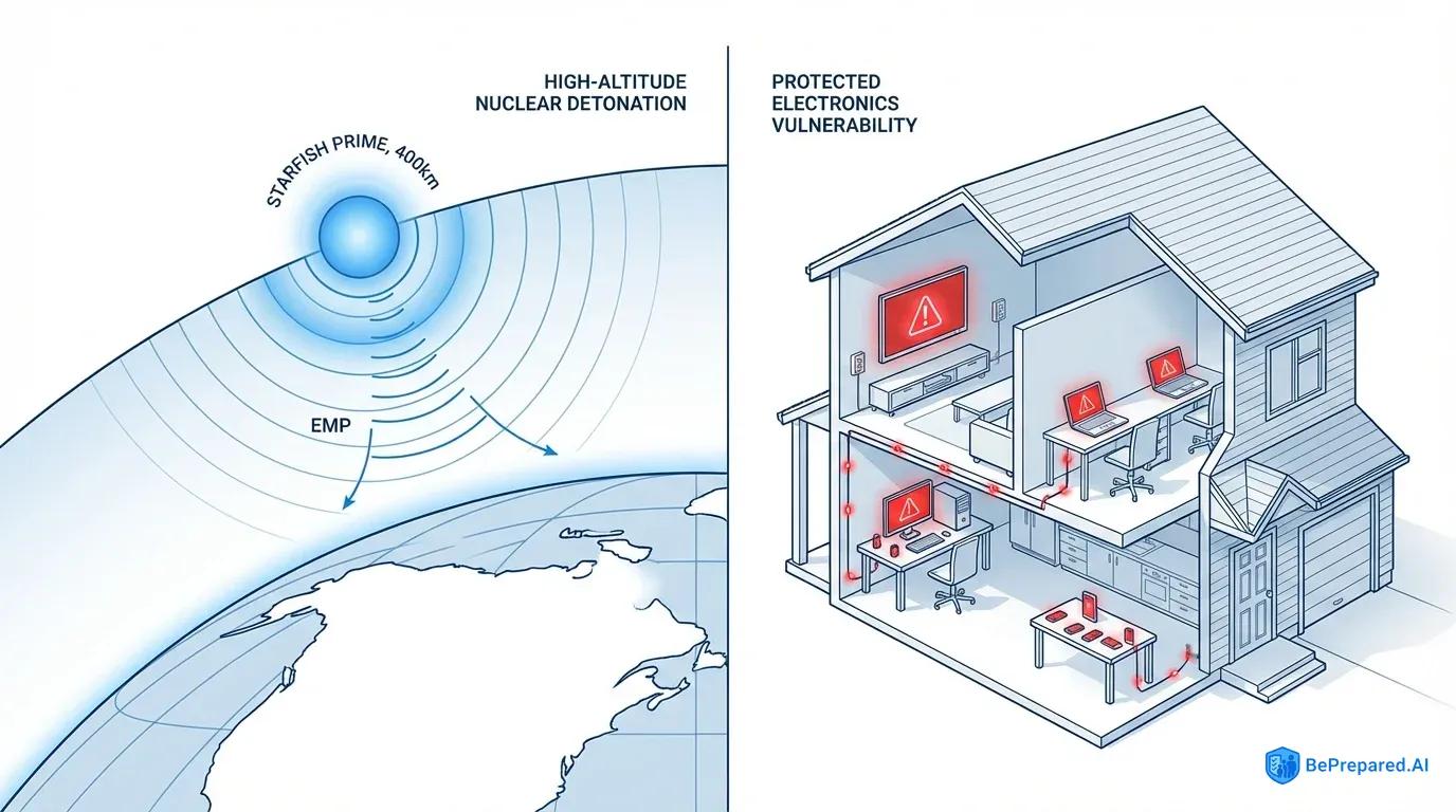
High-altitude electromagnetic pulse (HEMP) events occur when a nuclear device detonates 40 to 400 kilometers above Earth's surface, generating three distinct pulse components designated E1, E2, and E3 . The E1 component arrives first, delivering an incredibly fast-rising pulse measured in nanoseconds. This pulse couples directly into electronic circuits, overwhelming semiconductor junctions before protective devices can react. The E2 component resembles lightning in its characteristics but arrives during the chaos of E1 damage. The E3 component produces slower, longer-duration pulses similar to geomagnetic storms. These pulses induce currents in long transmission lines and potentially damage grid infrastructure.
Natural EMP events, primarily geomagnetic disturbances caused by solar activity, represent the second category. The 1859 Carrington Event demonstrated nature's capacity to generate electromagnetic chaos. Telegraph systems sparked, shocked operators, and continued functioning even after being disconnected from their batteries. Modern analysis suggests a Carrington-level event today would produce E3-like effects across vast geographic areas. However, it would lack the devastating E1 component that makes HEMP so particularly dangerous to solid-state electronics .
The third category encompasses non-nuclear EMP weapons, ranging from nation-state developments to theoretically portable devices. Their effective radius remains significantly smaller than HEMP events.
Your modern communication infrastructure faces profound vulnerability to these threats. The reasons extend far beyond simple electronic complexity. Contemporary devices rely almost exclusively on solid-state semiconductor technology—integrated circuits, microprocessors, and transistors built on silicon substrates with junction dimensions measured in nanometers.
These microscopic structures exhibit extreme sensitivity to voltage transients. Older vacuum tube technology could withstand significant overvoltage conditions due to the physical separation of elements and the robust nature of thermionic emission. Modern MOSFET and CMOS devices experience catastrophic failure when gate oxide layers just atoms thick encounter voltage spikes . The smartphone in your pocket, the software-defined radio on your desk, even the microcontroller in your backup generator—all contain thousands or millions of these vulnerable junctions.
The scope of potential communication disruption extends well beyond individual device failure. A significant HEMP event detonated at optimal altitude could affect electronics across entire regions spanning hundreds or even thousands of kilometers in radius . Within this footprint, the communication ecosystem collapses at multiple levels simultaneously.
Cellular networks fail as tower electronics fry and backhaul connections sever. Internet infrastructure dies as routers, switches, and servers succumb to induced currents. Even hardened emergency services communications experience degradation or complete failure depending on their protection status. The amateur radio operators who might provide crucial emergency communications discover their transceivers rendered inoperable. Their solid-state finals and receivers become expensive paperweights.
Critical systems in your home environment face cascading vulnerabilities that compound the communication challenge. Your primary communication devices—smartphones, computers, tablets, amateur radio equipment—represent obvious targets. The infrastructure supporting them proves equally susceptible. The commercial power grid, already vulnerable to E3 effects on long transmission lines, may experience widespread transformer damage and extended outages lasting months or years .
Your backup generator, if equipped with electronic ignition and voltage regulation, may refuse to start or operate. Solar charge controllers, inverters, and battery management systems all contain the same vulnerable semiconductors. Even receiving information becomes impossible when every radio, television, and computer within reach sits permanently disabled.
This comprehensive failure scenario demands protection strategies that address not just individual devices but entire communication systems with appropriate redundancy and shielding.
Core Components of an EMP-Resistant Communication System
Building genuine protection against electromagnetic pulse threats requires understanding four fundamental defensive layers. Each contributes essential capabilities to an integrated protection strategy. These components work synergistically—weakness in any single element compromises the entire system's survivability.
The physics governing EMP protection remains unforgiving, demanding attention to specifications, implementation details, and the interactions between protective elements.
Faraday cage construction forms the cornerstone of EMP protection, functioning through a principle discovered by Michael Faraday in 1836. When electromagnetic radiation encounters a conductive enclosure, it induces currents in that enclosure's surface. These induced currents generate their own electromagnetic fields that oppose and cancel the external field, preventing penetration into the interior volume.
The effectiveness of this shielding depends critically on several factors: the conductivity of the shield material, the thickness relative to skin depth at threat frequencies, and most importantly, the completeness of the enclosure. Proper Faraday cages require minimum 80dB attenuation across the threat spectrum . This spectrum spans from very low frequencies (E3 components starting below 1 Hz) through the extremely fast-rising E1 pulse with significant energy extending into the VHF range and beyond.
Achieving this performance demands continuous conductive enclosures without gaps exceeding one-twentieth of the wavelength at the highest frequency of concern. This typically means openings no larger than a few centimeters maximum.
The practical implementation of Faraday protection involves multiple approaches depending on scale and requirements. For small-scale protection of individual devices, nested metal containers provide effective shielding when properly prepared. A galvanized steel trash can with tight-fitting lid, itself placed within a second can with insulating material between layers, creates multiple shield boundaries.
Each boundary must maintain electrical continuity around its entire perimeter. The lid must make metal-to-metal contact with the can body around the full circumference. For room-scale protection, continuous copper or aluminum mesh installed over all six surfaces of the protected space provides comprehensive shielding.
The mesh openings must remain small relative to threat wavelengths, typically requiring 1/4 inch or finer grid spacing. All seams require overlap and bonding, creating electrical continuity across joints. Doors present particular challenges, necessitating fingerstock contacts or conductive gaskets that maintain shield integrity even as the door opens and closes.
Grounding systems serve dual purposes in EMP protection, though their implementation requires careful consideration of threat characteristics. For lightning protection and power surge mitigation, grounding provides a low-impedance path directing transient energy into the earth, away from protected equipment.
However, proper Faraday cage operation doesn't require grounding in the traditional sense. The shield functions by containing and redistributing electromagnetic energy across its surface, not by channeling it to earth . Improperly implemented ground connections can create vulnerabilities by providing paths for surge currents to enter the protected space.
The optimal approach involves isolating the Faraday cage from direct earth ground during the threat event while maintaining the ability to safely dissipate any charge accumulation. This typically means floating the shield or connecting it through high-impedance paths that block fast transients while allow slow charge equalization.
Proper grounding requires multiple paths to earth when protecting systems that must maintain external connections during operation . Your communication hub likely requires antenna connections, power feeds, and possibly network cables. Each represents a potential pathway for EMP energy to bypass the Faraday shield.
These penetrations demand careful treatment. All cable entries must maintain shield integrity through the use of feedthrough filters, surge arrestors, and proper bonding to the shield at the point of entry . The grounding system for these protective devices requires careful design.
Multiple paths to earth, implemented through ground rods driven to depth in moisture-rich soil and bonded together with heavy copper conductors, create a low-impedance ground plane. This ground plane serves as the reference point for surge protective devices, giving transient currents somewhere to go other than through your protected equipment.
Multiple surge protection layers including gas discharge tubes provide optimal protection against transients that couple into conductors entering the protected space . Gas discharge tubes form the first line of defense, capable of shunting enormous current surges—thousands of amperes—when voltage exceeds their breakdown threshold.
These devices respond relatively slowly compared to the nanosecond rise times of E1 pulses. However, their high current capacity makes them invaluable for clamping the largest surge components. Metal oxide varistors (MOVs) provide the second layer, responding faster than gas tubes and clamping voltage to levels that subsequent protection stages can handle.
The third layer employs transient voltage suppression (TVS) diodes or similar semiconductor-based protectors that respond in picoseconds. This speed proves fast enough to address even E1 rise times. This staged approach allows each layer to handle the portion of the threat it addresses best while protecting the subsequent, faster but more delicate layers from damage.
Power supply considerations extend beyond simple surge protection to encompass complete energy independence from the vulnerable grid. The ideal EMP-resistant communication system maintains operational capability even when commercial power disappears for extended periods. This requires robust backup power solutions designed with the same protection principles applied to communication equipment.
Deep-cycle batteries, particularly older flooded lead-acid designs without electronic battery management systems, provide EMP-resistant energy storage. Solar panels themselves generally survive EMP events—they're essentially large diodes with robust construction. The charge controllers regulating their output almost certainly won't unless protected.
Protecting a charge controller requires housing it within the Faraday cage or a separate shielded enclosure, complicating the system design. Alternatively, simple shunt-type charge controllers using older, more robust semiconductor technology may survive where modern MPPT controllers fail.
The remarkable EMP resistance of vacuum tube technology deserves particular attention when designing communication systems for post-EMP operation. Vacuum tube equipment shows inherent EMP resistance compared to solid-state devices due to fundamental differences in operating principles .
The electron flow in vacuum tubes occurs across physical gaps measured in millimeters, through high-vacuum environments, between mechanically robust electrodes. Voltage transients that would instantly destroy semiconductor junctions merely represent temporary perturbations to vacuum tube operation. The tubes themselves can handle significant overvoltage conditions.
Even if supporting components like power transformers or coupling capacitors suffer damage, these passive components are more easily replaced than integrated circuits. This inherent resistance makes vacuum tube amateur radio equipment, particularly vintage designs from the 1950s through 1970s, valuable components of EMP-resistant communication systems.
While not invulnerable—associated power supplies and control circuits may contain vulnerable components—properly maintained tube equipment stands far better survival odds than any modern solid-state transceiver.
- Foundation & Faraday Layer
- Reinforced concrete base (24" thick) with embedded copper mesh (10 gauge). Grounding rods at 8' depth minimum.
- EMP-Resistant Shell
- Double-layer steel plate walls (1/4" each) with dielectric barrier. Welded seams, RF-tight door frame specs.
- Power & Ventilation
- Independent circuit installation, EMP-hardened filters, redundant power systems. HEPA-grade air filtration.
- Communications Infrastructure
- Shielded cable entry points, waveguide installation specs, antenna feed-through requirements.
- Testing & Certification
- RF isolation testing procedures, EMP surge protection verification, security system validation protocols.
Implementation Guide: Building Your Protected Communications Hub
Selecting the appropriate room for your protected communications hub involves balancing multiple competing requirements while acknowledging the physical constraints of your home environment. The ideal location sits at or below ground level, where the earth itself provides additional electromagnetic shielding and where the building's structural elements offer protection from other threats.
Basements naturally excel in this role, particularly interior rooms without windows. A windowless room eliminates the need to shield large glass openings while providing structural walls on all sides that support shield installation. The space should measure at least 8 feet by 10 feet, providing sufficient room for equipment racks, operating positions, and the critical air gap between the Faraday shield and interior contents.
Beyond electromagnetic considerations, your communications hub requires environmental stability and accessibility. Avoid locations prone to flooding, as even minor water intrusion compromises both equipment and shielding effectiveness. The room should maintain moderate temperatures year-round without relying on electronic climate control systems that might fail during the very emergency requiring communication capability.
Proximity to your main living areas facilitates regular testing and maintenance while enabling rapid access during crisis situations. Consider the routing of antenna feedlines from this location to exterior antenna mounting points. Longer cable runs introduce additional signal loss and more penetrations requiring protection. These factors shouldn't override the fundamental importance of proper room selection.
Preparing the selected space begins with removing all non-essential items and addressing any moisture issues, damaged walls, or structural concerns. The room must become a clean slate for shield installation. Inspect electrical wiring carefully.
Existing circuits entering the room present both opportunity and risk—you'll need power, but each conductor penetrating the shield requires careful treatment. Consider whether to completely disconnect existing circuits and rely solely on protected power feeds, or to implement comprehensive surge protection on existing lines.
Map the locations of all utilities entering the space: electrical conduits, water pipes, HVAC ducts, and any other penetrations. Each represents a potential shield compromise requiring specific countermeasures.
Material selection for the Faraday shield itself involves choosing between copper and aluminum mesh, solid sheet materials, or hybrid approaches. Copper mesh offers advantages in conductivity, though aluminum provides benefits in cost and weight. For room-scale implementation, copper mesh with 1/4 inch or smaller openings, fabricated from wire at least 24 gauge, delivers excellent performance at reasonable cost.
Source this material from suppliers serving the EMI/RFI shielding industry rather than hardware store screening. Hardware store screening often contains gaps or breaks in the weave that compromise shielding effectiveness. Plan to install two complete layers with joints offset, creating redundancy and eliminating any gaps where single-layer seams might align.
Acquire the following materials before beginning construction. Stopping mid-installation to source additional supplies risks errors and incomplete shielding:
- Copper mesh in quantity sufficient to cover all six room surfaces twice, plus 20% extra for overlaps and errors
- Copper tape, 2 inches wide, with conductive adhesive for seaming
- Copper or brass wood screws, #8 size, in quantity sufficient for screw placement every 4 inches around all seams
- Copper or aluminum sheet material for creating the shielded door assembly
- Fingerstock or conductive gasket material for the door perimeter
- Copper grounding wire, #6 AWG minimum, for bonding
- Copper ground rods, 8 feet length, quantity of three minimum
- Exothermic welding kit or heavy-duty copper lugs and bolts for ground connections
- Insulating material for creating air gaps between shield and interior equipment
- Feedthrough filters and surge arrestors rated for communication frequencies you'll use
- Multimeter capable of measuring resistance in the milliohm range
- Non-conductive fasteners and standoffs for mounting equipment inside the shielded space
The step-by-step construction process begins with the room's floor, as this surface provides the foundation for all subsequent shield elements. Clear the floor completely, then roll out the first layer of copper mesh across the entire surface. Allow excess to run up the walls by at least 12 inches on all sides.
Subsequent wall installation will overlap this turned-up edge, creating continuous shield boundaries. Secure the floor mesh using non-conductive fasteners if necessary to prevent movement during construction. Install the second mesh layer perpendicular to the first, offsetting all seams by at least 12 inches from first-layer seams. Bond the two layers together at multiple points using copper screws or rivets, creating electrical continuity between layers.
Wall shield installation proceeds systematically around the room perimeter. Starting at one corner, unroll copper mesh vertically from the ceiling to the floor. Allow the bottom edge to overlap the floor shield's turned-up edge by at least 6 inches. Secure the mesh to wall studs or furring strips using copper screws at 4-inch intervals vertically.
The mesh must maintain contact with the floor shield along the entire bottom edge. As you progress around the room, overlap each new mesh section over the previous section by at least 4 inches. Bond the overlap every 4 inches with copper screws. At corners, fold the mesh around the corner rather than creating a seam at this critical junction. Apply copper tape over all seams, burnishing it firmly to ensure metal-to-metal contact with the mesh on both sides of the seam.
The ceiling shield follows the same principles as walls and floor. Install mesh across the entire ceiling surface in two layers with offset seams. Overlap the top edges of wall shields by at least 6 inches on all sides. This overlap creates a continuous conductive enclosure—the Faraday cage—with no gaps exceeding the mesh opening size.
Bond ceiling-to-wall overlaps every 4 inches around the entire perimeter using copper screws that penetrate both ceiling mesh and wall mesh. This creates mechanical and electrical connection. Apply copper tape over these critical seams for additional redundancy.
Door construction presents the most challenging aspect of room-scale Faraday cage implementation. The door must maintain shield integrity while allowing access. The simplest approach involves covering a solid-core wood door with copper or aluminum sheet material, creating a conductive surface that mates with the shield wall surface through conductive gasket material.
Cut sheet copper or aluminum to cover the door's interior face completely, overlapping the edges by 2 inches on all sides. Secure the sheet material using copper or aluminum screws at 4-inch spacing around the perimeter and across the surface. Install fingerstock or conductive gasket material around the entire door frame. Position it so the conductive door surface compresses the gasket when closed, creating metal-to-metal contact around the full perimeter.
The door's hinges and latch mechanism require special attention. Standard steel hinges may create adequate contact, but adding copper braiding jumpers between door and frame ensures electrical continuity even as hinges wear. Install at least two braided jumpers, one near the top hinge and one near the bottom. Use copper screws to attach the braid firmly to both door shield and frame shield.
The latch mechanism should pull the door tightly against the gasket material when closed. Consider multiple latch points around the perimeter for large doors, ensuring even compression of the conductive gasket.
All penetrations through the shield for power, antennas, or other utilities require careful treatment to maintain shield integrity. Before installing any feedthrough components, establish the grounding system. Drive three 8-foot copper ground rods into the earth outside the building, spacing them at least 10 feet apart in a triangular pattern.
Connect these rods together using #6 AWG bare copper wire, creating a ground ring. Bond this ring to your home's existing electrical ground system, maintaining the multiple ground paths. Run a #6 AWG copper conductor from this ground system into the communications room, bonding it to the Faraday shield at the point where penetrations will enter.
Install feedthrough filters and surge arrestors in a metal box bonded directly to the Faraday shield at each penetration point. The box itself becomes part of the shield, with the protected cable entering from inside the Faraday cage and the unprotected cable entering from outside. Bond the surge arrestor ground terminals to both the penetration box and the main ground conductor using heavy copper wire with minimal length.
For antenna connections, install a multi-stage protection system: a gas discharge tube rated for the antenna impedance (typically 50 or 75 ohms), followed by a quarter-wave stub that shorts transient energy to ground while appearing as an open circuit at operating frequencies, followed by a ferrite bead or small inductor that blocks fast transients while passing desired signals.
Testing the completed shield requires both DC continuity measurements and RF shielding effectiveness verification. Using a multimeter set to measure resistance, verify that any two points on the shield surface show less than 0.01 ohms resistance between them. This confirms continuous electrical connection throughout the shield structure.
Pay particular attention to seams, corners, and the door perimeter, as these locations present the highest risk of poor contact. For RF testing, place a portable FM radio tuned to a strong local station inside the completed shield with the door closed. The signal should disappear completely or reduce to barely detectable levels.
Similarly, place a cell phone inside the shield and attempt to call it from outside. The call should fail to connect, indicating the shield blocks cellular frequencies effectively.
After confirming shield integrity, install interior equipment mounting systems using non-conductive standoffs that maintain air gaps between equipment and the shield surfaces. This prevents direct electrical contact that could allow transient currents to flow through equipment cases. Wooden shelving, plastic racks, or metal racks mounted on insulating standoffs all work effectively.
Plan your interior layout to maximize accessibility while maintaining the required air gaps. Leave space for comfortable operation of radios and other equipment, as this room may serve as your primary communication center during extended emergencies.
Equipment Selection and Configuration
Choosing the specific communication equipment to protect within your hardened hub requires balancing multiple factors: inherent EMP resistance, operational capability across likely emergency scenarios, power requirements compatible with backup systems, and your own skill level in operating and maintaining the equipment.
The equipment selection process should begin with a clear-eyed assessment of communication needs during various emergency scenarios. These range from short-term grid-down situations requiring local coordination to extended catastrophic events where long-distance communication becomes essential for information gathering and coordination with distant family or mutual assistance groups.
Vacuum tube equipment shows inherent EMP resistance compared to solid-state devices, making them the preferred choice for primary communication equipment in EMP-protected systems . Vintage amateur radio transceivers from manufacturers like Collins, Drake, Hallicrafters, and Heathkit, produced during the 1950s through 1970s, represent the sweet spot of tube technology.
These designs offer mature engineering with excellent performance, relatively compact packaging compared to earlier equipment, and widespread availability in the used market. A Collins KWM-2 or Drake TR-4, for example, provides comprehensive HF coverage with both transmit and receive capability across amateur bands, SSB and CW modes, and power output sufficient for reliable communication during poor propagation conditions.
These transceivers typically consume 200-400 watts during transmission, manageable from backup power systems. Power consumption during receive mode remains higher than modern solid-state equipment.
The comparison between vacuum tube and solid-state equipment extends beyond EMP resistance to practical operational considerations. Tube equipment requires warm-up time—typically one to three minutes after power application before transmission should begin. This allows cathode heaters to reach operating temperature and prevents cathode stripping.
This warm-up requirement poses no significant problem in emergency communication scenarios where you're not attempting to respond to immediate calls. Tube finals require tuning for each frequency change, a process taking 30 seconds to a few minutes depending on equipment and operator skill. This compares to the instant frequency changes of modern synthesized radios.
However, this tuning process provides valuable feedback about antenna system performance and propagation conditions. This information helps optimize communication effectiveness.
Maintenance requirements differ significantly between technologies. Vacuum tubes eventually wear out, with typical lifetimes ranging from 2,000 to 10,000 hours depending on tube type and operating conditions. Stocking spare tubes for your equipment, particularly finals and driver stages that experience the most stress, ensures long-term operational capability.
These tubes remain available from both new-old-stock suppliers and manufacturers still producing common types for industrial and audiophile markets. Conversely, solid-state equipment that survives the initial EMP event may continue operating for years with minimal maintenance. When semiconductor devices fail, replacement often requires specialized knowledge and equipment beyond most operators' capabilities.
For operators committed to modern solid-state equipment despite its vulnerability, or as backup systems to primary tube equipment, careful selection and protection strategies mitigate risk. Choose radios with simple, robust designs rather than feature-laden models packed with vulnerable microprocessors.
Older solid-state transceivers from the 1980s and early 1990s, before the widespread adoption of DSP and microcontroller-based designs, offer better survival prospects than current models. A Yaesu FT-757GX or ICOM IC-735, for instance, uses discrete semiconductors and analog circuitry for most functions, with minimal microprocessor involvement.
Store these radios in nested Faraday cages—a metal equipment case inside a metal box, with insulation between layers—when not in use. Maintain multiple identical units if possible, recognizing that even with protection, solid-state equipment faces higher failure probability than tube gear.
Communication system redundancy extends beyond simply having backup radios to encompassing diverse communication modes and frequency ranges. Your protected equipment suite should include HF capability for long-distance communication, VHF/UHF capability for local and regional communication, and possibly shortwave receivers for information gathering from broadcast stations worldwide.
An HF tube transceiver addresses long-distance needs. A VHF/UHF handheld transceiver, preferably an older model with minimal microprocessor control, provides local communication. Store this handheld in a nested Faraday cage when not in use. A standalone shortwave receiver, particularly tube-type models like the Hallicrafters SX-100 or Collins 51J series, enables monitoring of international broadcasts, time standard stations, and other information sources.
Maintaining multiple redundant systems can increase survival probability through statistical advantage. If each protected system has a reasonable survival probability (accounting for protection effectiveness and inherent resistance), having two or three independent systems improves overall system resilience. This redundancy should include not just duplicate equipment but diversity in protection methods and storage locations.
One HF transceiver might reside in the main communications hub, while an identical backup sits in a separate Faraday cage in a different building or buried cache. Different protection methods—room-scale shielding, nested metal containers, underground storage—face different potential failure modes. Diversifying protection approaches increases overall system resilience.
Antenna systems require protection strategies distinct from equipment protection, as antennas must remain connected to the outside world to function. The antenna itself, being a passive conductor, generally survives EMP events undamaged. The transmission line connecting antenna to radio, however, acts as a collector for electromagnetic energy, conducting potentially destructive surges directly to your transceiver's input.
Proper antenna protection requires multi-stage surge suppression implemented at the point where feedline enters the protected space. Install a lightning arrestor or gas discharge tube rated for your feedline impedance (typically 50 ohms) at the building entry point. Bond the ground side to your grounding system using the shortest possible conductor.
Inside the building but outside the Faraday cage, install a second surge arrestor. At the Faraday cage penetration, install a feedthrough filter that passes desired frequencies while blocking transients, followed by a final gas discharge tube inside the cage.
This multi-stage approach addresses the different components of EMP threats. The exterior arrestor shunts the largest surge components to ground before they enter the building. The second stage catches transients that bypass the first arrestor or that couple into the feedline between the first arrestor and the building.
The feedthrough filter blocks high-frequency transient energy while passing desired communication frequencies. The final interior arrestor provides last-resort protection if all previous stages fail or if transients couple through the filter. Each stage protects the subsequent stage from damage while contributing to overall system protection.
Antenna selection itself influences vulnerability to EMP effects. Simple wire antennas—dipoles, end-fed wires, long wires—present minimal vulnerable components. The antenna wire itself survives, and simple wire-to-coax connections using quality connectors introduce no vulnerable electronics.
Beam antennas like Yagis or quads similarly use passive elements, though metal-to-metal connections at the driven element and any matching networks require attention. Avoid antennas with active components like preamplifiers or remote antenna tuners unless these components can be housed in protected enclosures or you maintain spares in Faraday cages.
Consider installing multiple antennas for different bands and purposes, with switching systems that allow selecting antennas without exposing equipment to unprotected feedlines. A multi-position coaxial switch with all positions except the selected one grounded provides this capability while offering additional protection.
Power supply configuration for EMP-resistant communication systems must address both the immediate post-event period and extended operations during grid-down scenarios. The ideal system operates independently of commercial power indefinitely. Deep-cycle battery banks provide the foundation, storing energy for radio operation and essential lighting.
Flooded lead-acid batteries, particularly industrial or forklift batteries, offer excellent capacity, proven longevity, and inherent EMP resistance due to their simple electrochemical operation without control electronics. Consider sizing the battery bank to provide several days of operation at your expected duty cycle.
If you plan to operate a 100-watt transceiver at 50% duty cycle (half transmitting, half receiving) for 8 hours daily, you'll need approximately 400 watt-hours per day. For three days, this requires 1,200 watt-hours. At 12 volts, this translates to 100 amp-hours of battery capacity. Doubling this capacity helps avoid deep discharge that reduces battery life.
Solar panels provide sustainable recharging for battery banks, but the charge controller presents vulnerability. Protect a spare charge controller in a Faraday cage, installed and connected only after the EMP event. Alternatively, design the system to allow temporary direct charging from solar panels to batteries during emergencies, accepting the risk of overcharging in exchange for operational capability.
Include a simple voltmeter to monitor battery voltage during direct charging, disconnecting panels when voltage reaches safe limits. For longer-term operation, the protected charge controller can be installed to resume proper charging management.
Ready to implement comprehensive EMP protection for your communication systems? Download our Complete EMP Protection System Checklist for detailed material specifications, step-by-step installation procedures, and testing protocols that ensure your protected communication hub will function when you need it most. This comprehensive checklist includes specific part numbers for critical components, supplier recommendations, and troubleshooting guides for common installation challenges.
The configuration of protected equipment within your communications hub should prioritize operational efficiency and testing convenience. Mount primary equipment at comfortable operating height, with clear access to controls and displays. Position backup equipment nearby but separately, allowing independent testing without disturbing primary systems.
Maintain detailed logs of all equipment serial numbers, tube types and replacement dates, and performance baselines established during regular testing. These logs prove invaluable during troubleshooting and when sourcing replacement components.
Regular testing schedules ensure your protected systems remain operational and your skills stay current. Monthly testing should include powering up all equipment, making contact on various bands and modes, and verifying that antenna systems and power supplies perform as expected.
Annual testing should include comprehensive checks of Faraday cage integrity, surge arrestor functionality, and battery system capacity. Replace batteries according to manufacturer recommendations or when capacity testing reveals degradation below 80% of rated capacity. Rotate vacuum tubes between primary and backup equipment to equalize wear, extending overall system lifetime.
The investment in EMP-resistant communication systems extends beyond equipment and materials to encompass knowledge and skills. Vacuum tube equipment requires understanding of different operating procedures compared to modern solid-state radios. Antenna theory, propagation characteristics, and emergency communication protocols all demand study and practice.
Participate in amateur radio emergency exercises, ARES/RACES activities, and field day operations to develop proficiency with your equipment under realistic conditions. The most sophisticated protected communication system provides no value if you lack the knowledge to operate it effectively when commercial communication infrastructure fails and your community depends on your capability to send and receive critical information.
Your protected communication hub represents a significant investment of resources, time, and effort. This investment purchases something invaluable: the capability to maintain contact with the outside world, coordinate with family and community members, and gather information necessary for informed decision-making during the most challenging scenarios.
When electromagnetic pulse events—whether from natural or man-made sources—silence the communication systems that modern society takes for granted, your protected systems will continue functioning. They will provide the information lifeline that transforms survival from desperate isolation into coordinated resilience.